Wiring Diagram For Ignition System
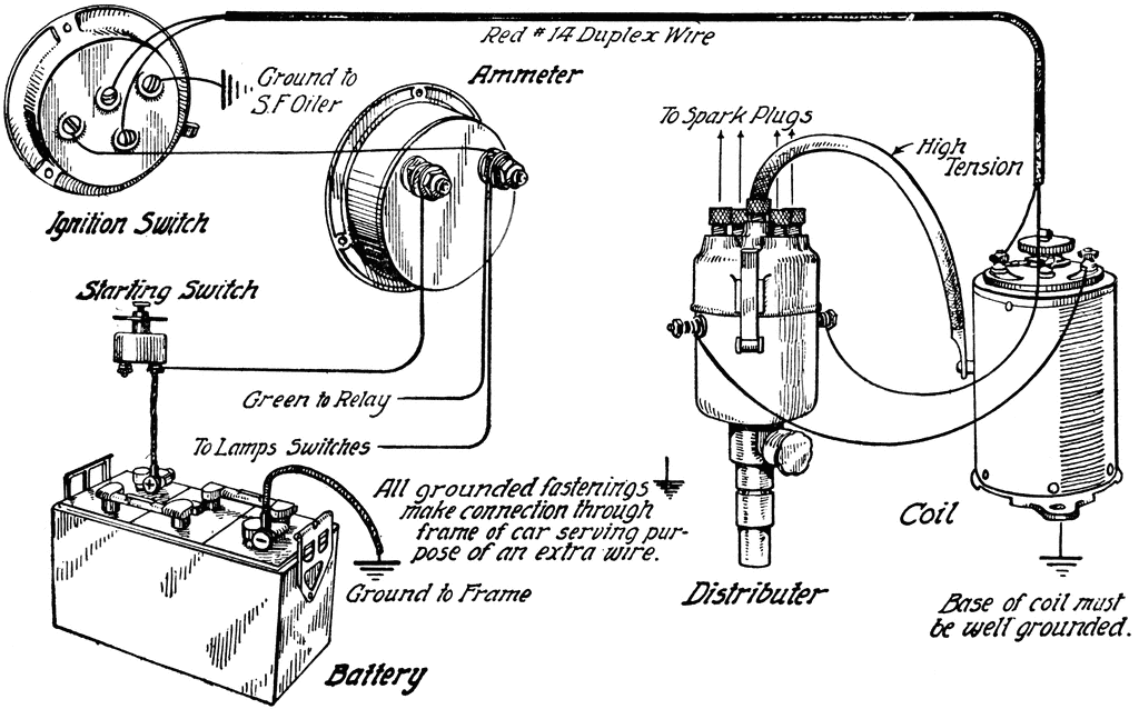
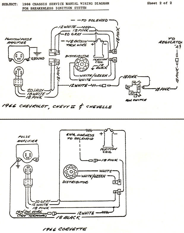
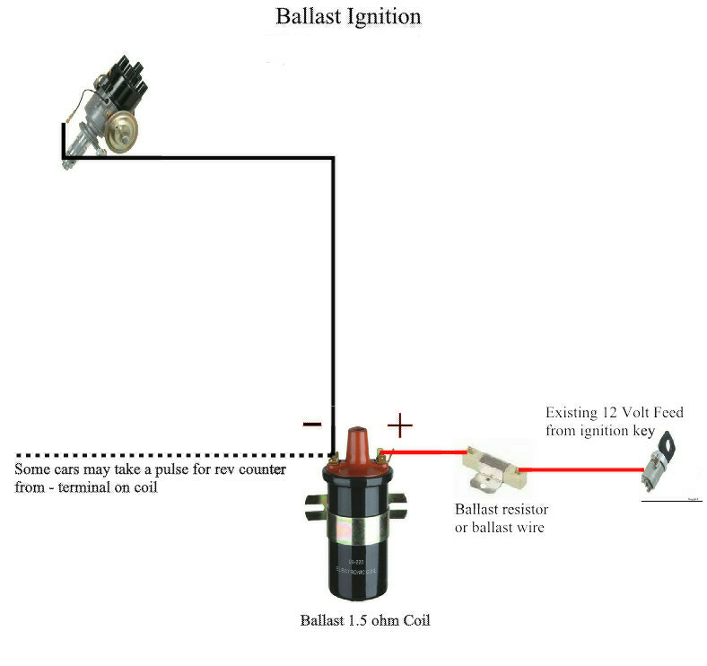
Wiring diagram for ignition system. Figure 5 28 Breaker Point Ignition Wiring Diagram. Basic ignition switch wiring diagram thanks for visiting our site this is images about basic ignition switch wiring diagram posted by maria rodriquez in basic category on may 06 2019. Basic ignition system wiring diagram.
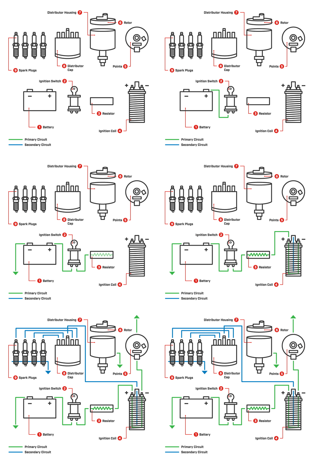
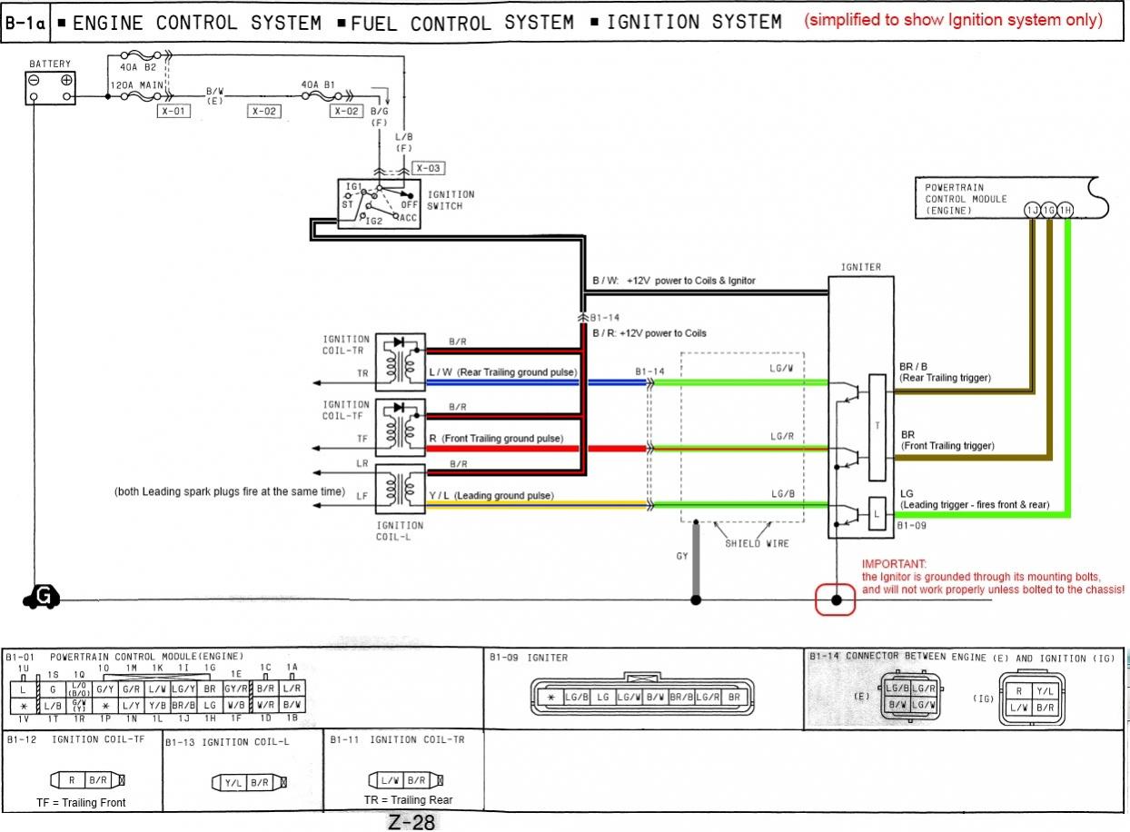
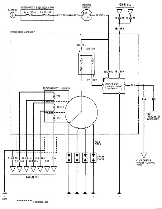
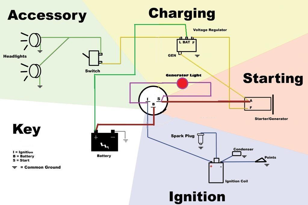
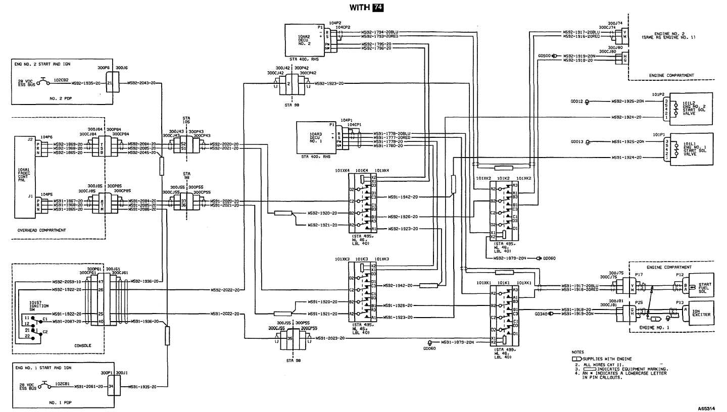
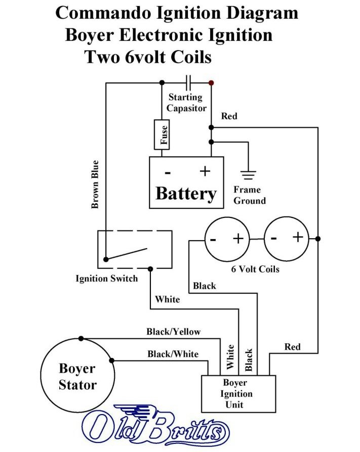
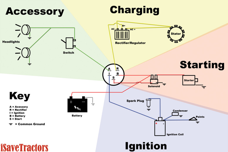
An ignition switch wiring diagram provides the schematics that are needed to enable auto owners to fix any wiring repairs related to their ignition system. It consists of a battery ignition switch electronic control unit magnetic pick-up reluctor or armature ignition coil distributor and spark plugs. This diagram was designed for 12 volt systems but can also be used for 6 volt systems.
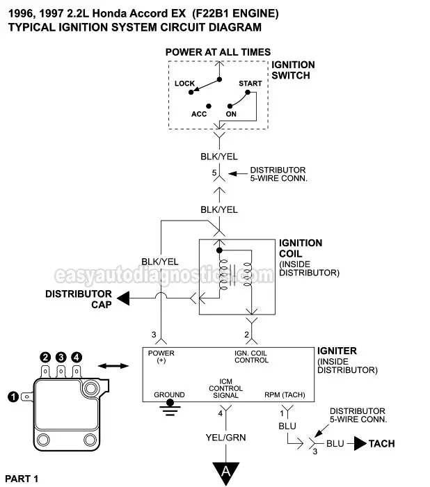
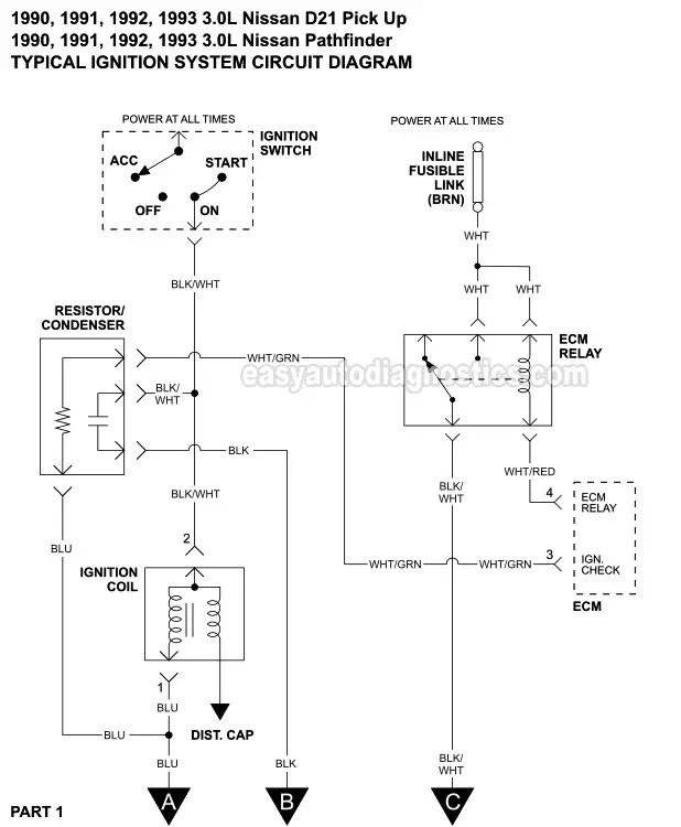
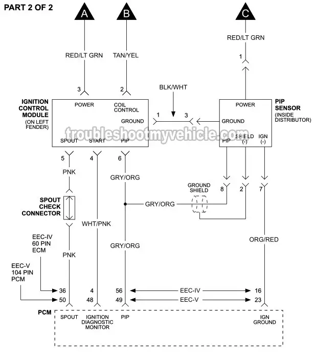
It shows the components of the circuit as simplified shapes and the skill and signal associates in the middle of the devices. A schematic diagram of an electronic ignition system is shown in Figure 236. Part 1 Ignition System Wiring Diagram 1999 2002 3 3l Nissan Quest.
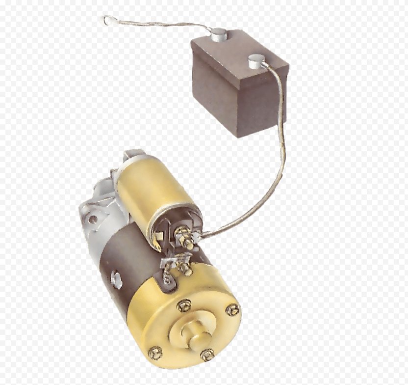
I get no click or any noise from starter - Answered by a verified MercedesThis is a complete database of Mercedes-Benz wiring diagrams. Need starting system wiring diagram for sl have no crank condition. Collection of simple ignition wiring diagram.
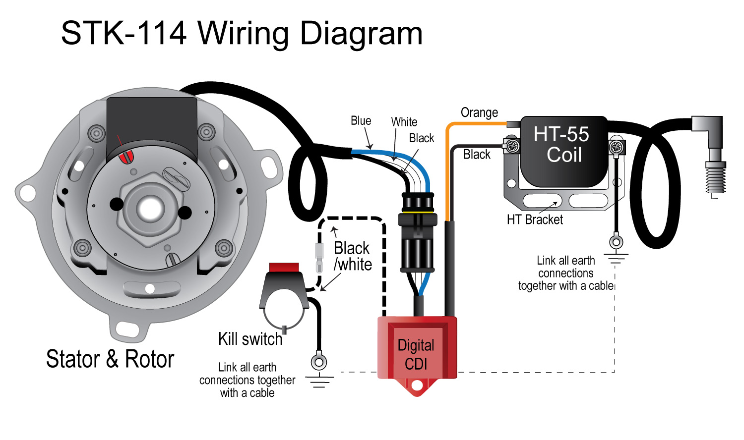
Construction of Electronic Ignition System. The wiring diagram shown below was obtained from Pertronix to show the proper hookup for a Pertronix. Ignition system basics matt dubanoski accuspark wiring diagrams systems a short course to help you understand 1929 6v 12v diagram 3 typical car starting t x how read the cj2a page wire motorcycle basic your boat for ford 9n 2n 8n converting 12 volt simple capacitive discharge 4 pole starter solenoid works conversion led rocker switch faraday s law and auto simplified vape installation work.
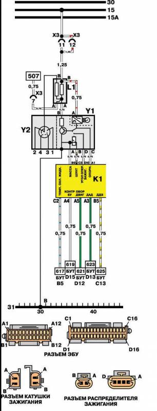
Installing The SS HI 4N Ignition xlch bobber new build repair rigid. A wiring diagram is a streamlined traditional pictorial representation of an electrical circuit. It reveals the elements of the circuit as simplified forms and the power and also signal links between the tools.
23 Turn 48 Switch-over valve ignition advance. A top view of the regulator is shown in diagram below to help with terminal.
Collection of simple ignition wiring diagram.
It shows the components of the circuit as simplified shapes and the power and signal connections between the devices. It shows the parts of the circuit as streamlined shapes and also the power and also signal connections in between the gadgets. Part 1 Ignition System Wiring Diagram 1999 2002 3 3l Nissan Quest. An ignition switch wiring diagram provides the schematics that are needed to enable auto owners to fix any wiring repairs related to their ignition system. This diagram was designed for 12 volt systems but can also be used for 6 volt systems. It reveals the elements of the circuit as simplified forms and the power and also signal links between the tools. Basic Points Ignition Wiring Diagram wiring diagram is a simplified satisfactory pictorial representation of an electrical circuit. It consists of a battery ignition switch electronic control unit magnetic pick-up reluctor or armature ignition coil distributor and spark plugs. The wiring diagram shown below was obtained from Pertronix to show the proper hookup for a Pertronix.
A wiring diagram is a streamlined conventional photographic depiction of an electric circuit. The green LED LED2 connected in the output section lights up with back emf and therefore it should be connected with reverse polarity as shown in Fig. Youll have to consult your Repair Manuals wiring diagrams to see where this fuse andor relay is located and replace as necessary. You can find the ignition system wiring for the 1994-1995 Ford E150 E250 E350 vans here. Figure 5 28 Breaker Point Ignition Wiring Diagram. Ignition System Circuit Diagram 1996-1999 ChevyGMC Pick Up And SUV This typical circuit diagram of the ignition coil ignition control module camshaft and crankshaft position sensors applies to the 1996 1997 1998 1999 ChevroletGMC 1500 2500 and 3500 Pick Ups equipped with a 43L V6 or a 50L v8 or a 58L V8 engine. 2004 ford Explorer Ignition Wiring Diagram wiring diagram is a simplified welcome pictorial representation of an electrical circuit.














Post a Comment for "Wiring Diagram For Ignition System"